ANSI B16.5 ASTM A182 Alloy 321 Pad Flange Raised Face 8″ Class 150

- PRODUCT DETAIL
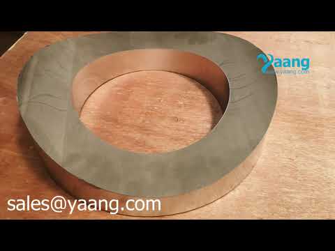
Type: Alloy 321 Pad Flange
Material: Alloy 321 (UNS S32100)
Standard: ANSI B16.5
Pressure: Class150
Size: DN200 (8″)
What is Studding Outlet Flange?
Studding Outlet Flanges are usually designed to be installed in the inside or outside of vessels and tanks. The curving of the outlet should be ordered to fit the curvature of the shell, head, or pipe. These flanges can come in sizes from ½ inches to 24 inches, and the pressure ratings of 150# to 2500#. (All classes 150# – 300# should have a raised face of 1/16” and classes above that should be raised face. They can be ordered in Carbon Steel, Stainless Steel, and alloy steel. A common alternative name for studding outlets is “pad flange.” To clarify, the pad flange and the studding outlet are the same part and pad flanges are not a variation of studding outlet.
Composition ranges for Alloy 321 (UNS S32100/1.4541)
| Cr | Ni | Mo | Cu | Ti | C | Mn | Si | P | S | N | Fe | |
|---|---|---|---|---|---|---|---|---|---|---|---|---|
| MIN | 17.0 | 9.0 | – | – | 5x(C+N) | – | – | 0.25 | – | – | – | – |
| MAX | 19.0 | 12.0 | 0.75 | 0.75 | 0.70 | 0.08 | 2.0 | 1.0 | 0.04 | 0.03 | 0.1 | Bal |
Mechanical Properties for Alloy 321 (UNS S32100/1.4541)
Average Elevated Temperature Tensile Properties
| Temperature, °F | Ultimate Tensile Strength, ksi | .2% Yield Strength, ksi |
|---|---|---|
| 68 | 84 | 38 |
| 400 | 62 | 20.5 |
| 600 | 62 | 18 |
| 800 | 62 | 17 |
| 1000 | 59.5 | 16.5 |
| 1200 | 45.5 | 16 |
| 1400 | 27.5 | 14 |

FLANGE – STUDDING OUTLET, ANSI CLASS 150, B16.5 (IN)
| Pipe Size
(NPS)
|
Outside
Diameter of Flange
|
Thickness
of Flange
|
Diameter
of Raised Face
|
Bolt
Circle Diameter
|
Hole Size
HS
|
Number
of Bolt Holes
|
Hole Depth | Tap Size | Threads Per Inch T.P.I | Tap Depth | Flat
Bottom Approx. Weight
|
|
|---|---|---|---|---|---|---|---|---|---|---|---|---|
| B | O | T | R | C | U | V | Base | per 1″ | ||||
| 1/2 | 3.5 | 1.25 | 1.38 | 2.38 | 27/64 | 4 | 0.88 | 1/2 | 13 | 0.56 | 3 | 2.7 |
| 3/4 | 3.88 | 1.25 | 1.69 | 2.75 | 27/64 | 4 | 0.88 | 1/2 | 13 | 0.56 | 3.7 | 3.2 |
| 1 | 4.25 | 1.25 | 2 | 3.12 | 27/64 | 4 | 0.88 | 1/2 | 13 | 0.56 | 4.3 | 3.8 |
| 1 1/4 | 4.62 | 1.25 | 2.5 | 3.5 | 27/64 | 4 | 0.88 | 1/2 | 13 | 0.56 | 5.1 | 4.4 |
| 1 1/2 | 5 | 1.25 | 2.88 | 3.88 | 27/64 | 4 | 0.88 | 1/2 | 13 | 0.56 | 5.9 | 5.1 |
| 2 | 6 | 1.5 | 3.62 | 4.75 | 17/32 | 4 | 1.12 | 5/8 | 11 | 0.75 | 10.2 | 7.1 |
| 2 1/2 | 7 | 1.5 | 4.12 | 5.5 | 17/32 | 4 | 1.12 | 5/8 | 11 | 0.75 | 14 | 9.5 |
| 3 | 7.5 | 1.5 | 5 | 6 | 17/32 | 4 | 1.12 | 5/8 | 11 | 0.75 | 15 | 11 |
| 3 1/2 | 8.5 | 1.5 | 5.5 | 7 | 17/32 | 8 | 1.12 | 5/8 | 11 | 0.75 | 19 | 13 |
| 4 | 9 | 1.5 | 6.19 | 7.5 | 17/32 | 8 | 1.12 | 5/8 | 11 | 0.75 | 20 | 14 |
| 5 | 10 | 1.75 | 7.31 | 8.5 | 21/32 | 8 | 1.31 | 3/4 | 10 | 0.88 | 28 | 17 |
| 6 | 11 | 1.75 | 8.5 | 9.5 | 21/32 | 8 | 1.31 | 3/4 | 10 | 0.88 | 31 | 19 |
| 8 | 13.5 | 1.75 | 10.62 | 11.75 | 21/32 | 8 | 1.31 | 3/4 | 10 | 0.88 | 46 | 26 |
| 10 | 16 | 1.81 | 12.75 | 14.25 | 49/64 | 12 | 1.44 | 7/8 | 9 | 1 | 58 | 35 |
| 12 | 19 | 1.81 | 15 | 17 | 49/64 | 12 | 1.44 | 7/8 | 9 | 1 | 83 | 48 |
| 14 | 21 | 2 | 16.25 | 18.75 | 7/8 | 12 | 1.56 | 1 | 8 | 1.12 | 102 | 55 |
| 16 | 23.5 | 2 | 18.5 | 21.25 | 7/8 | 16 | 1.56 | 1 | 8 | 1.12 | 123 | 66 |
| 18 | 25 | 2.25 | 21 | 22.75 | 1 | 16 | 1.81 | 1 1/8 | 8 | 1.25 | 140 | 67 |
| 20 | 27.5 | 2.25 | 23 | 25 | 1 | 20 | 1.81 | 1 1/8 | 8 | 1.25 | 166 | 79 |
| 24 | 32 | 2.5 | 27.25 | 29.5 | 1 1/8 | 20 | 2.12 | 1 1/4 | 8 | 1.44 | 231 | 100 |
Note:
- Material: Studding Outlets are most commonly provided in SA-105. They can also be made from a full range of stainless and alloy materials.
- Thickness: The standard thickness shown above for all studding outlets is the minimum required per ASME Section VIII Division I Paragraph UG-43(d) for thread engagement and an ID mount. It is important to note that each individual application should be analyzed for proper thickness.
- Facing: The Studding Outlet minimum thickness “T” includes proper raised face per ANSI B16.5. Outlets can be supplied with any special facing as needed upon request.
- Drilling and Tapping: Studding Outlets are furnished to ANSI B16.5 specifications unless otherwise specified. Thread depth is in accordance with ASME Section VIII Division I Para. UG-43(g) for a design temperature not to exceed 650oF, a base metal stress of 17,500 psi(g), and a stud stress of 25,000 psi(g). All other materials exceeding these stresses should be checked for UG-43 compliance.
- Bore: Bore sizes shown above are standard. Other sizes can be furnished upon request.
- Curving: Connections can be furnished contoured to fit any shell, head, or cone at additional cost. Specify diameter to be mounted.
NEXT: ASME B16.5 ASTM B564 Hastelloy B3 Blind Flange RF DN250 150LB